 Fraunhofer Institute for Integrated Systems and Device Technology IISB
Etching Simulator ANETCH
Introduction
Accurate modeling of pattern transfer by lithography followed by dry etching becomes increasingly important for microelectronic fabrication as feature sizes shrink and the geometry of active and passive devices significantly influences performance and reliability. Predictive simulation of etching profile evolution requires coupling of reactor-scale simulation with feature-scale simulation.
Our simulator ANETCH supports arbitrary 3D mask shapes as they can be obtained e.g. by 3D lithography simulation. ANETCH allows the simulation of reactive ion etching with different chemistries as well as of pure physical sputter etching.
Examples for Results
Sputter etching
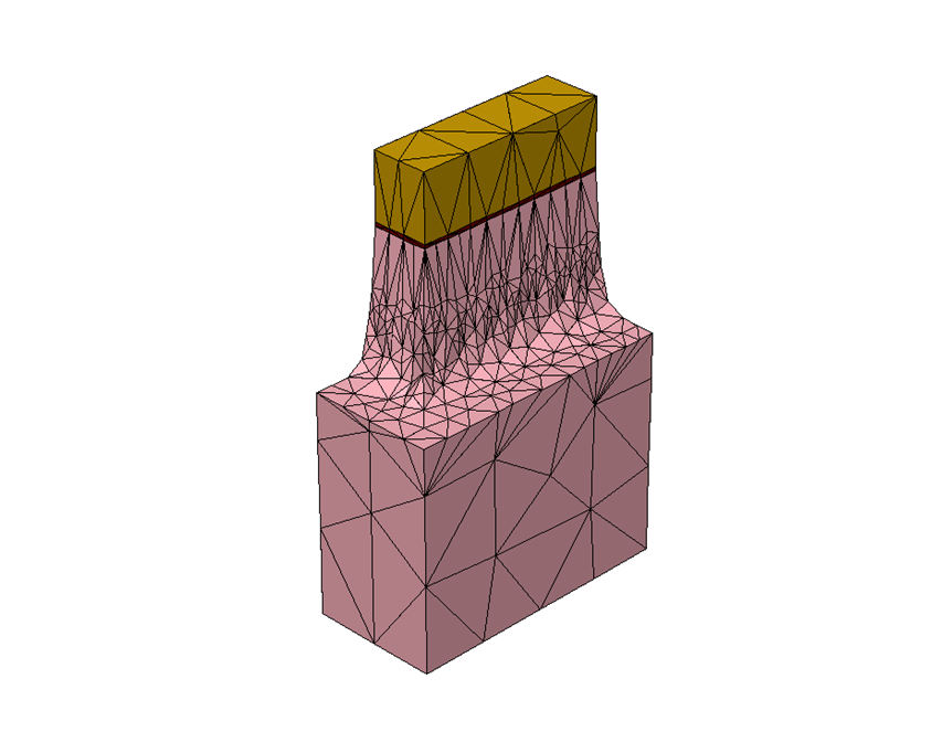
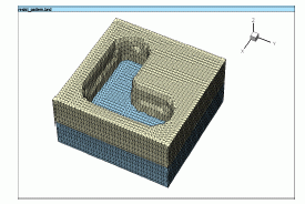
We consider an L-shaped trench which requires 3D treatment both in terms of particle transport modeling and surface representation. The initial geometry (Figure 1) has been obtained by lithography simulation. For sputter etching, as considered here, the etch rate is determined by the local flux of ions and the socalled sputter yield which is defined as the number of atoms sputtered per incident ion. The surface update is carried out in a sequence of steps in order to allow re-calculation of the local etch rates which vary with the changing geometry. We used ion angular distributions (IAD) of Ar that have been obtained by equipment simulation for varying process conditions.
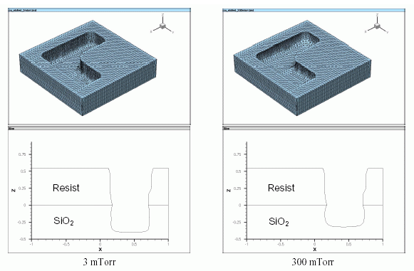
Figure 2 shows the simulation results for etching at 3 mTorr and 300 mTorr. In both cases, an etched depth of 0.4 µm for unshadowed positions has been specified. The underetching is more pronounced for the higher pressure which is due to the relatively higher number of ions with larger incident angles. Also the bottom shapes of the etched trenches differ due to the different IADs. For the IAD at 300 mTorr shadowing caused by the trench mask has a stronger effect than for the narrower distribution at 3 mTorr, thus leading to a reduced etch depth for the higher pressure.
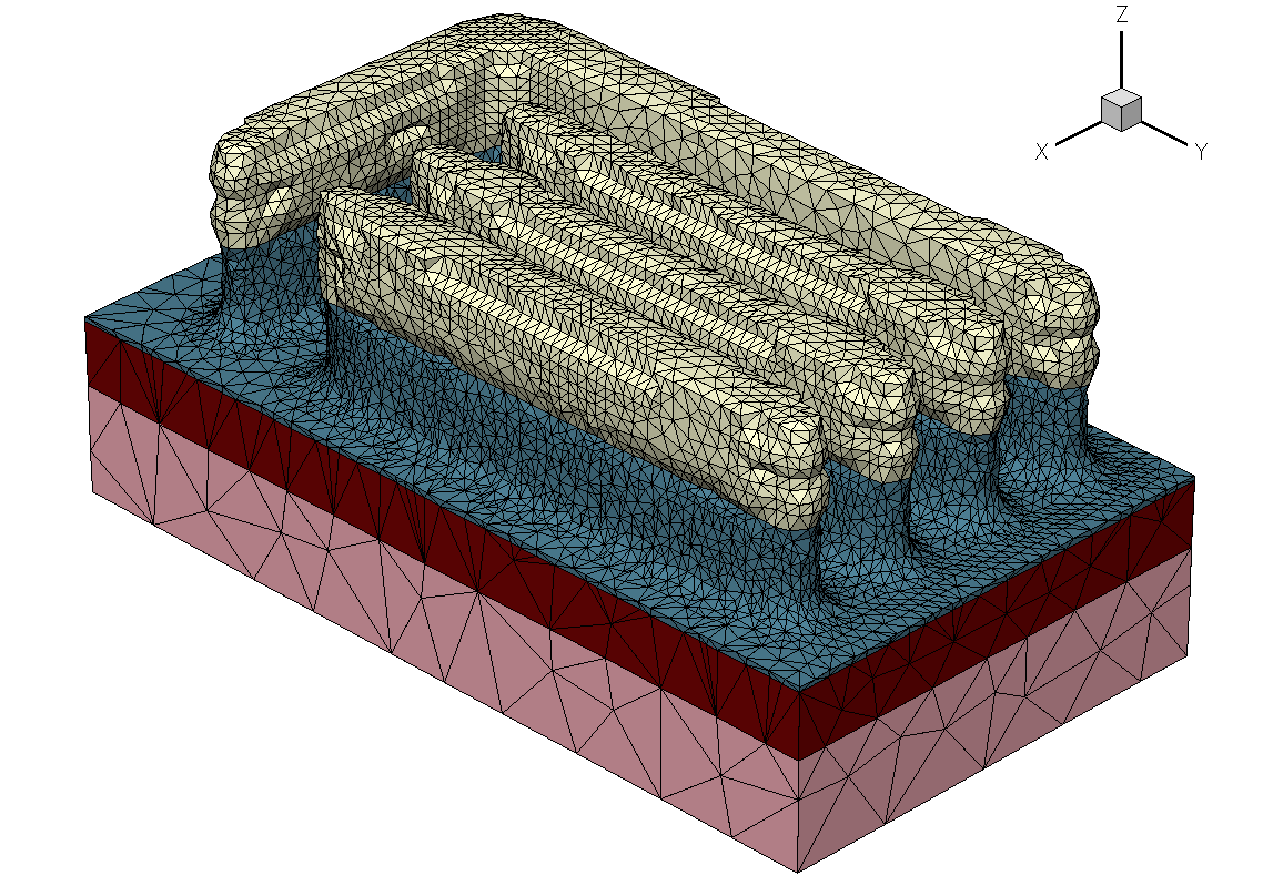
Figure 3 shows the result of a coupled lithography and etching simulation for a more complex layout (lines-elbow structure).