Optimization of Complex Heat Sink Structures

Common high performance cooling solutions for power electronics consist of heat sinks with arrays of in-line or staggered pin fins under forced convection with a coolant fluid. An optimal heat sink design is thereby determined by various objectives, for example a high heat transfer capability while having a small pressure drop.

Within our research group AI-augmented Simulation, we work on and apply various optimization methods to meet individual objectives and requirements for a given heat sink application.

Figure 1: Optimization of a 5 pin fin array with a locally varying heat source under each pin. Though the heat flux is set to 0.5 W/mm² for all setups, different optimal shape modifications emerge with different optimization potential.

Shape Optimization of Heat Sink Structures

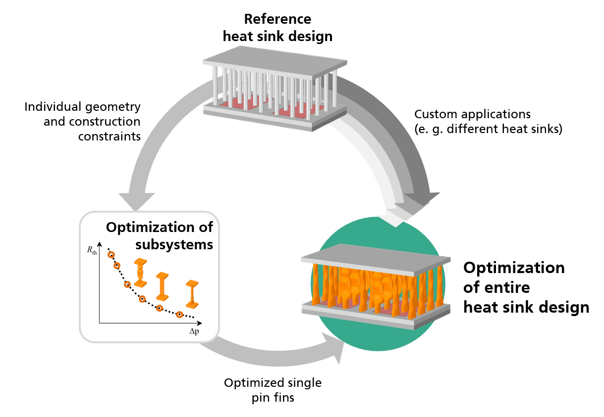
A promising method to improve heat sink designs is shape optimization. Though implementations already exist for some simulation tools, the usage for industrial applications is not yet feasible since it requires adjustments of the methodology and comprehensive understanding of the theory and numerical limitations. Therefore, the shape optimization approach is further developed, adapted and applied for the design of efficient heat sinks in the field of power electronics cooling.

This approach enables optimization beyond standard and general assumptions by taking application specific boundary conditions into account. Based on conjugate convective heat transfer simulations, the shape of the heat sink structure is thereby iteratively morphed to match the objective goals and custom constraints.

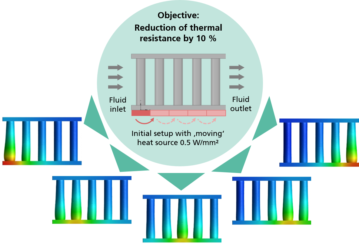
When considering individual local distributions of the heat sources, various optimal shape modifications of the heat sink may emerge having different optimization potential. This is shown in Figure 1, where the thermal resistance of a pin fin array with different heat source locations is reduced by 10 % each. This becomes even more relevant for applications such as avionics, with high demands on the heat sink efficiency, as well as a lightweight and compact design.

Figure 2: Optimization of an individual heat sink design on subsystem level and of the entire heat sink with respect to custom applications

Customized Optimization of Established Heat Sinks

In another optimization approach, established heat sink designs are further optimized considering unique boundary conditions within individual applications. Here, instead of optimizing an entire pin fin heat sink using many extensive CFD simulations, a simplified thermal model with artificial boundary conditions is combined with efficient genetic algorithm (GA) techniques to attain an optimal arrangement of the pin fins (see Figure 2).

Due to its small computation and implementation effort, the method is suited to find feasible initial setups for extensive shape optimization studies. Especially when considering complex heat sinks, the number of design iterations and the computation time can be reduced.