Projects

HoskA - 9-Phase Automotive SiC-Inverter

Within the project HoskA, a SiC-based 9-phase automotive inverter based on B6-powercores was developed. The powercores include the DCB-based powermodules with SiC-MOSFETs and SEMIKRON SKiN technology, the gate driver, the DC-link capacitor as well as current and temperature sensors.

Using three B6 powercores in parallel, a symmetrical 9-phase 150 kW electric drive with a phase displacement of 40 degree of the PMSM was realized. The modularization concept allows also the realization of 50 kW (3-phase) and 100 kW (6-phase) drive systems using one or two identical powercores.

Project partners: Volkswagen AktiengesellschaftSemikronTDK, LiebherrFederal Ministry of Education and ResearchVDI|VDE|IT

Download Product Sheet HoskA - 9-phase automotive SiC-Inverter"

6-Phase SiC-Inverter for Automotive Application

Siliconcarbide (SiC) MOSFETs offer huge potentials for power electronic systems due to their significantly reduced conduction and switching losses and their capability for highest junction temperatures. Based on this semiconductor technology, a modular and compact 6-phase 800 V drive-inverter for automotive application with a maximum output power of 300 kW was designed and realized. Using four parallel MOSFETs per switch, the system provides a maximum phase current of 150 Arms.

The inverter demonstrates the advantages of SiC-semiconductors on system level:

  • Highest power density
  • Highest (part-load) and drive-cycle efficiency
  • Highest switching frequency
  • Reduced cooling effort

Due to possible switching frequencies of up to 100 kHz, the SiC-inverter is suitable for machines and applications with highest electric frequencies like high-speed traction-motors, compressors and electric turbochargers.
Download Product Sheet "100 kW SiC-Inverter for automotive application"

60 kW SiC-Inverter for Fuel-Cell Air-Compressor

High-speed electric motors like the compressor-motor for fuel cell air supplies require higher inverter output-frequencies and therefore higher switching-frequencies to avoid additional losses within the machine. With state-of-the-art inverter systems (e.g. using Si-IGBTs and Si-diodes) the switching frequency is typically limited to values of 10 to 20 kHz due to higher switching losses.

In order to meet these demands, a 60 kW inverter system for high-speed electric machines was developed. The use of SiC 1200 V MOSFETs, ceramic DC-link capacitors and a low inductive system design allow switching frequencies up to 100 kHz at reasonable efficiencies.
An overall power-density of the power-stage of >150 kW/l was achieved. This offers the possibility to integrate the inverter directly into the fuel-cell air supply system.

Download Product Sheet " 60 kW SiC-Inverter for High-Speed Drives"

6-Phase Electric Machine with 175 kW for 800 V

Within the LZE-project Fraunhofer IISB developed a 6-phase automotive traction motor with 175kW for a nominal DC-voltage of 800 V. Highest power density with a maximum motor speed of 20.000 rpm.

  • Permanent magnet synchronous machine with buried magnets
  • Specification based on automotive traction motors
  • Usable in 3- and 6-phase connection
  • Segmented magnets
Peak Power 175 kW
Topology PMSM, 3/6-phase
Max. speed 20.000 rpm
Max. torque 230 Nm
Max. phase current 280 Arms
Nominale ZK-Spannung 800 VDC
Stator length 150 mm


COSIVU – Integrated 1200 V SiC-Inverter for Commercial Vehicles

Fraunhofer IISB developed an integrated 1200 V inverter in cooperation with the COSIVU project partners. The inverter is used in an electric drive unit for commercial vehicles of Volvo. The inverter uses highly efficient SiC transistors which raise the part load and drive-cycle efficiency of the system significantly.

A modular and flexible design allows also the realization of a 6-phase inverter system.

Technical data:

Max. output power 290 kVA
Nom. input voltage range 600 VDC to 800 VDC
Max. phase current 300 Arms
Switching frequency 10 kHz to 16 kHz
10 kHz to 16 kHz Modular B6


Project Partners: Volvo TechnologyHella, TranSiC, SensitecNanotestElapheSwereaTU Chemnitz and Fraunhofer ENAS

Download Product Sheet "COSIVU"

The research has been conducted within the project 'COSIVU', funded by the European Commission under grant agreement number 313980.

Project Duration: 2012 - 2014

EMiLE

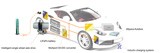
Electric motor integrated power electronics with Smart Stator Teeth (SST)

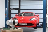
Within the EMiLE project, ten partners from the German industry and research-institutes are working on innovative drivetrain solutions for tomorrow's e-mobility. The project focusses on compact and efficient electric vehicle traction-drives with a high degree of integration of electric machine, power electronics, and gearing, which are perspectively suitable for large scale production. High power density, high efficiency and cost minimization are benefits of the realized Smart Stator Tooth - structure within the drive unit. Each stator segment of the PMSM electric machine has its own individual control and power electronics. The modular system approach can be adapted to different vehicle and drive classes.

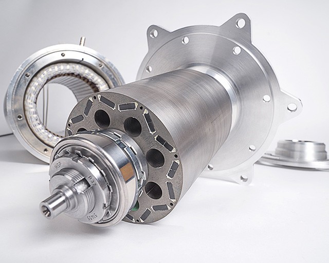
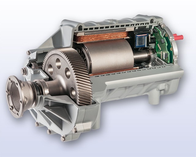
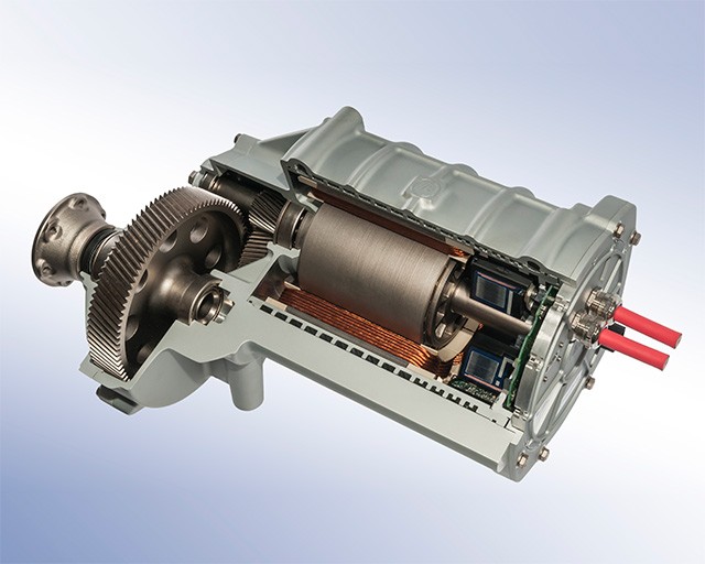
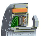
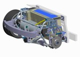
Drivetrain with Smart Stator Teeth

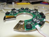
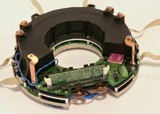
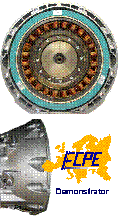
Each Smart Stator Tooth (SST) consists of a motor segment and an electronics assembly. Twelve SST form one PMSM stator and the corresponding inverter.
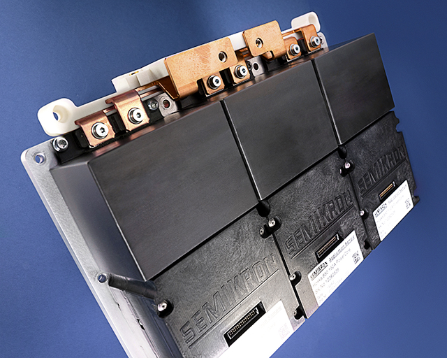
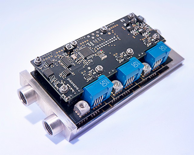
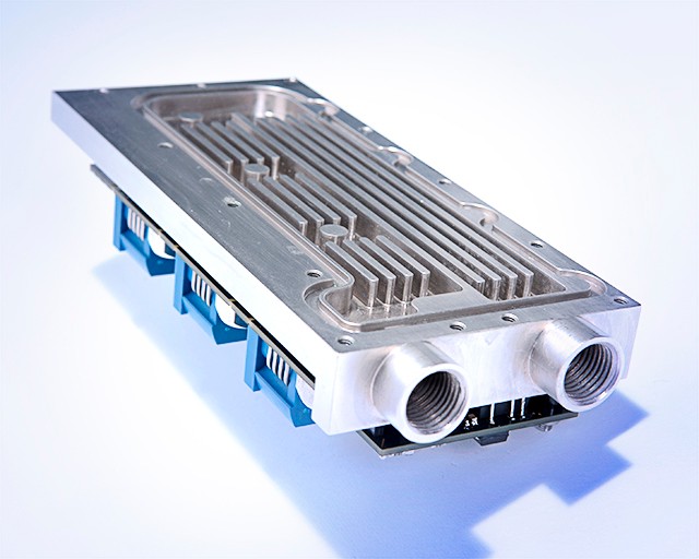
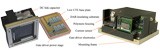
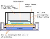
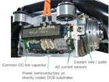
Each tooth electronic consists of an IGBT full bridge power-module, phase current sensor, current control loop, gate driver unit, and a fault detection block. The stator windings are directly connected to the AC terminals of the power module, thus minimizing space and reducing the number of parts. The pre-assembled SST is fully testable before mounting the complete system.

Novel Control and Safety Functions

The advanced SST control functionalities have two objectives: First, a failure in one phase power module does not lead to a full system failure. Second, after detecting faulty parts, the remaining SST are used to actively compensate the influence of the failure.
The SST concept redefines and improves both availability and failure mitigation: The aim is to achieve a safe system state, concerning vehicle stability and passenger safety, without additional hardware effort. At the same time, the availability is increased, which means that partial faults do not stop the whole system.


Project Partners:  VDI|VDE|ITAix ControlBoschInfineoniSEA RWTH AachenLenzeSiemensTDK-EPCVWZF

Funding: German Federal Ministry for Education and Research  

Download Product Sheet "EMiLE - Electric motor integrated power electronics"

Inverter Building Block

New generation of automotive power modules with innovative electric/thermal interfaces and joining technologies.

A new design for power modules for the use in hybrid and electric vehicles was developed. Many of the weak-points of today’s solutions regarding interfaces, constraints for the overall system design, the assembly effort and reliability could be eliminated. The result was the realization and testing of a modular ‘Inverter Building Block’.

State-of-the-art inverter designs have for example an interface between the power-modules and the DC-link capacitor. Constructional constraints regarding the component placement can lead to a high impedance of the commutation cell, especially for integrated drive solutions. The placement of the DC link foil capacitor in the ‘Inverter Building Block’ leads to a high switching performance of the module, independent from the overall 3D-inverter design. This provides also improvements in the fields of robustness (overvoltage margin), EMC behavior and energy efficiency (reduction of switching losses). Also, the gate driver and the current sensor are integrated in the module. An LTCC device with integrated gate resistors and the power stage of the gate driver is directly soldered on the well cooled DAB substrate (Direct Aluminum Bonding). This reduces parasitic effects and typical thermal hot spots.

Integrating power electronic components in mechanical drives leads to a higher level of thermal and mechanical stress compared to stand-alone solutions. To reduce the thermo-mechanical stress within the module, an all-aluminum material concept was used. Also the material weight and costs as well as the susceptibility to corrosion are minimized by the consequent use of aluminum based materials. Innovative joining technologies, like laser welding of the aluminum terminals with the DAB substrate and double-sided nanosilver sintering of the semiconductor devices, were investigated. Power cycling and passive temperature cycling tests have shown a significant improvement of the number of cycles before failure compared to standard technology.

The design of the ‘Inverter Building Block’ allows the modular use in a variety of drive and motor configurations (e.g. in single or double motor setups). A first test of the design was carried out in an axle drive system that was developed in the same project.

Project Partners: Fraunhofer Institutes: IFAM, IKTS, ILT, IMS, IZM, ISIT

Project Duration: 2009 - 2011

High Performance Integrated e-Drive

© Fraunhofer IISB

Single wheel traction drive for fully electric vehicles with integrated inverters

A single wheel axle drive unit has been developed that includes two mechanically independent permanent magnet synchronous motors (PMSM) with a reduction gear (7:1). Each motor has a peak-power of 80 kW and a continuous power of 30 kW. The maximum torque per wheel is 2000 Nm. The chosen ‘off-axis’ concept allows a flexible use in a variety of vehicle concepts, for example in small commercial vans, busses or sports cars.

Six ‘Inverter Building Blocks’ are used to realize the double-inverter for the drive unit with a nominal phase current of 350 Arms and a nominal DC link voltage of 400 V. The two independent field-oriented control algorithms are implemented on a central control board with a TriCoreTM processor. Communication to the superior vehicle control system is realized via CAN bus. This allows an independent torque control for each wheel of the axle. An advanced safety architecture is implemented to meet the ASIL-D safety requirements.

The power electronic components including the ‘Inverter Building Blocks’, the controller and the DC busbars are completely integrated into the electric drive. This reduces the required space, the costs and also leads to an improved EMC behavior. A direct connection of the motor AC cables without additional connectors and the common use of one cooling circuit for the two electric machines and the power electronic amongst other things reduce the material and production costs.

Project Partners: SPN Schwaben Präzision Fritz Hopf GmbHMACCON

Project Duration: 2009 - 2011

Product Sheet: High Performance Traction-Drive (2x 80 kW) with Integrated Inverter

FSEM - Fraunhofer Systemforschung Elektromobilität

Integrated drive inverter for wheel hub motors

In the context of the project ’FSEM - Fraunhofer Systemforschung Elektromobilität’ a drive inverter for the application in wheel hub motors with a DC-link voltage of 400 V was developed at the Fraunhofer IISB.

The drive inverter that is fully integrated into the wheel-hub motor generates a frequency variable alternating current out of the direct current of the traction battery (nominal DC-link voltage = 400 V). Thus, a continuous power of 30 kW and a peak power of 65 kW are available at each motor. The drive inverter located between battery and motor, developed at the IISB for this application, is integrated into the external rotor motor without requiring additional construction space. The integration of the drive inverter into the motor offers the possibility of a common use of the existing motor cooling circuit. The expected electromagnetic emissions should be reduced because of the shielding effect of the metallic motor housing in which the drive inverter is placed. The structure of the system is redundant because of its realization as two three-phase partial machines in one wheel-hub motor. If one motor or one phase fails, the system can be operated with half power.

Special demands concerning construction, contacting and thermal behavior are made regarding the integration of power electronics into the motor. High requirements concerning robustness and vibration resistance of the drive inverter are necessary because of the integration into the unsprung area of the vehicle. All loads occurring to the wheel directly affect the drive inverter. To meet these high requirements among others, the power connections to the DCBs have been realized with wire bonding. By means of thermal simulations of motor and drive inverter during the development phase, the thermal behavior of the system has been characterized and optimized in advance.

Project Duration: 2009 - 2011

Hybrid Traction Unit

Electric drive unit with two independent induction machines and an integrated double inverter for the use in axle-split hybrids or small electric vehicles.

The developed integrated drive unit includes two induction machines with a nominal power of 20 kW for each motor and a maximum torque of 80 Nm up to a motor rotational speed of 2500 1/min. Two planetary reduction gears (ratio 6:1) are used to achieve the required torque of about 500 Nm at each wheel. Each of the two mechanical independent motors powers one wheel of the electrified axle with an individual torque regulation realized by two implemented field oriented controls (FOC) running on the system's control board. Due to the compact system design, the drive unit can be installed in the rear axle at the installation space that is, e.g. in a 4WD car like the Audi TT quattro, originally intended for the mechanical differential. Depending on the used energy storage, the system is suitable for small electric vehicles or for hybrid vehicles with a conventional combustion engine powering the other axle of the car (axle-split hybrid).

The unit’s double inverter is installed directly at the housing of the electric machines and uses a common cooling jacket with the motor for the six half-bridge IGBT modules. The control board, which is based on the Infineon TricoreTM, and the common DC link foil capacitor for both inverters are placed above the power-modules.

The specifications of the integrated double inverter are:

  • Apparent output power (each inverter): 45 kVA
  • Switching frequency: 10 kHz
  • Nominal DC link voltage: 400 V
  • DC-link capacitor: 0.5 mF
  • Direct cooled DCB/DAB substrates (ECPE/FhG WO 2007/090664)
  • Infineon IGBT 3
  • Infineon EmConTM diodes
  • AC-current measurement: open loop hall effect sensors

Project Partners: Oswald E-Motors, HEYNAU

Project Duration: 2008 - 2010

Electric Drive Technology Platform

© Fraunhoder IISB
Grafik
© Fraunhofer IISB
Foto
© Fraunhofer IISB
CAD Model

Development of a street legal electric vehicle fully equipped with Fraunhofer IISB components for traction power, electric and thermal energy management and charging.

Fraunhofer IISB is developing various research platforms for the evaluation and optimization of hybrid and elec­tric vehicle powertrain components. The elec­tric vehicle platform is based on an ARTEGA GT.

Research focuses within this vehicle project are:

  • Operational strategy with variable DC link voltage for increase of part-load efficiency
  • Position-tolerant inductive charging
  • Model-based vehicle control system using Matlab/Simulink and dSpace
  • Advanced vehicle safety architecture
  • Overall thermal management
  • Street legality

An integrated central drive unit with two independent electric machines and a maximum power output of 2x 80 kW allows an independent torque allocation for each wheel of the rear axle.

All converters necessary for electrical energy manage­ment, power supply and charging are integrated into the energy storage which therefore transforms into a smart battery unit. This kind of system partitioning fol­lows the basic idea of a "site-of-action integration" and mini­mizes high voltage cable harness and system costs.

An innovative multiport DC/DC con­ver­ter is used in the electric vehicle platform for managing the high voltage electrical system. This allows a flexible combination of dif­fe­rent energy storages with different volt­age levels (e.g., a traction battery with additional supercap storage).

Project Partners: Open technology platform without restrictive contractual obligations to certain companies from the automotive industry (in-house research project).

Participation of interested companies is possible (e.g. in the form of introducing and testing their own devices, components and technologies - as well as becoming a sponsor).

ECPE Demonstrator Project "System Integrated Drive for Hybrid Traction"

© Fraunhofer IISB

Integration of a 50kW electric drive together with the power electronics in the clutch bell of a passenger car.

The project aims to research and test new technologies and techniques that allow the integration of power electronics in particularly demanding environments, such as the drive train of hybrid cars. Against this background, the system integration of power electronics brings with it a requirement profile that requires the resolution of traditional interfaces between electronics and mechanics as well as the abandonment of well-trodden paths in assembly technologies, component technologies and assembly processes.

Due to the very close dependencies between mechanical design, material selection, heat dissipation, reliability, EMC behaviour, manufacturability, testability and costs, system development is only possible in an interdisciplinary development team of experienced engineers from electrical engineering, mechanical engineering and materials science.

The Fraunhofer IISB as a „Competence Center Automotive“ of the European Center for Power Electronics e.V. (ECPE) carried out this project on behalf of the ECPE GmbH.

With the help of new approaches for 3D integration of power electronics into complex mechanical structures, the development of innovative passive components and power modules and optimized thermal management, it has been possible to integrate a inverter with a record power density of 75 kW/dm³ into the extraordinarily demanding installation space. Details of the work are ECPE-confidential.

Challenges:

  • Coolant temperatures up to 115°C
  • Ambient temperature up to 140°C
  • High currents (approx. 300A) and voltages (approx. 400V)
  • High vibration and thermal cycling loads
  • Very small and rugged installation space
  • High reliability requirements
  • Perspectives for cost-effective manufacturability

Project Partners: ECPE

Project Duration: 2004 - 2007